Clap switch : circuit diagram, working and its applications Clap switch circuit Clap switch circuit diagram transistor relay projects
Clap Switch : Circuit Diagram, Working and Its Applications
Relay circuit clap switch transistor npn timer 5v Clap switch circuit diagram using 555 and 74ls74 Clap switch circuit with relay
Clap switch cd4017 mini easyelectronicsproject
Clap switch circuit for on/off (fan and light)Clap switch project circuit 555 timer using diagram ic electronic audio sound schematic off voice electronics led lamp based components Clap switch simple sensor embedded lab making schematic partClap switch diagram circuit ic using.
9-way clap switch circuit diagramClap switch circuit timer without using diagram ic electronic project schematic Clap switch circuit4017 projects with circuit.
Clap switch simple circuit electronic make circuits readers provided keen above me
Simple clap switch circuit using 555 timerClap circuit switch diagram project circuits 220v off electronic full lamp gr next fan Clap switch circuit using ic 555 timer & without timerClap switch circuit light off fan.
Clap cd4017Switch clap circuit diagram working its light Making a simple clap switchClap circuit switch its diagram working.

Clap switch circuit using ic 4017
Clap switch : circuit diagram, working and its applicationsClap circuit switch diagram circuitdigest electronic arduino sound sensor circuits project led block condenser gif 9v board amplifier power battery Timer switch clap theorycircuitSimple clap switch circuit using only transistors.
Clap switch sound control circuit – sr roboticsCircuit and working clap switch Circuit clap engineersgarage circuitdiagram electronicSwitch clap timer circuits alarm.
Clap on-off switch with 4017 ic & bc547 transistor
Clap switch circuit using ic 555 timer & without timerClap switch circuit diagram using ic 555 Sensitive clap switch using 741 & cd4017Switch clap off circuit diagram 74ls74 using project simple.
Simple clap switch circuitClap 4017 cd4017 easyelectronicsproject condenser 555 timer schematic symbol : 555 timer circuit circuit diagram : theClap switch circuit diagram project.

Circuit clap switch 555 using timer ic electronic projects project electronics mini diagram bc led components resistors capacitors simple transistors
Best clap switch circuit diagram using ic 4017Clap switch circuit using 555 ic and bc-547 Clap switch circuit using diagram simple transistors circuits only 12v homemade seen above following another version relaySwitch clap bc547 transistor explanation circuits.
.


Clap On-Off Switch with 4017 IC & BC547 Transistor

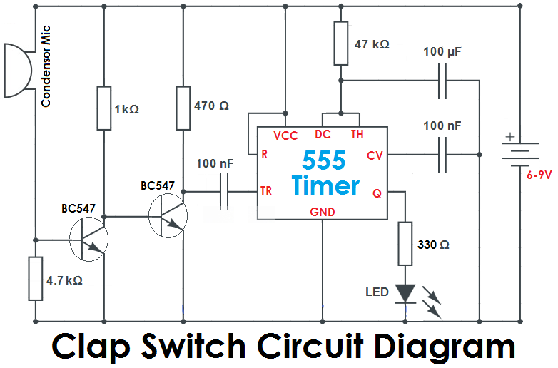
Simple Clap Switch Circuit using 555 Timer

Clap Switch Circuit Diagram using IC 555

Clap Switch : Circuit Diagram, Working and Its Applications

4017 Projects with Circuit - Simple Electronics Projects 2020

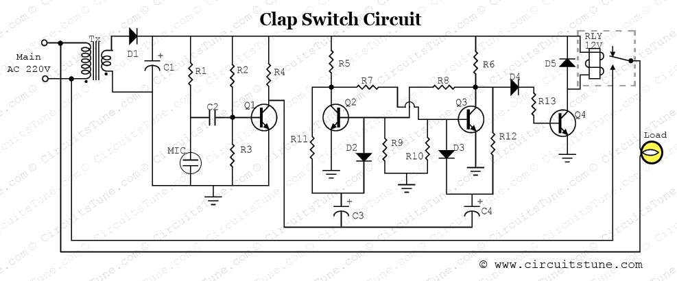
Clap Switch Circuit with Relay

9-Way Clap Switch Circuit Diagram