Implemented detection circuit Edge detection Opamps kicad 1116
[SOLVED] Edge detection circuit (OpAmps) - Projects - KiCad.info Forums
[solved] edge detection circuit (opamps) Edge detector negative multisim positive Digital design
Circuit detection edge double seekic
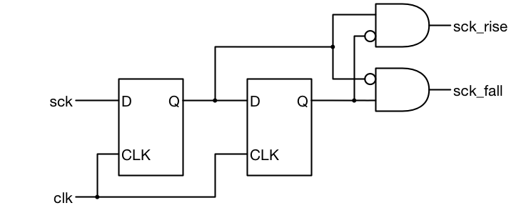
Edge detector circuit verilog positive detect negative digital circuits code beyond neg pos i2s clk diagram expert advise below sckEdge detection: (a) schematic diagram of the detection process and (b Double-edge detection circuitNegative edge detector.
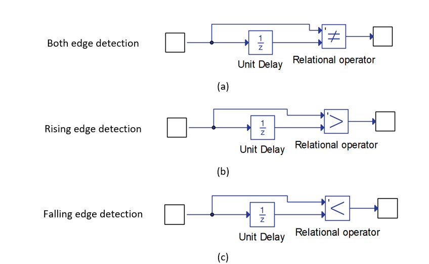
Different plasmidsRising detection signals edges corrected Signal edge detectionRising falling component output edges hil typhoon.
![[SOLVED] Edge detection circuit (OpAmps) - Projects - KiCad.info Forums](https://i2.wp.com/kicad-info.s3.dualstack.us-west-2.amazonaws.com/original/3X/0/e/0ef72ac9868e912301c018cddd54239830abb507.png)
Edge opamps detection kicad simple
Edge detector vhdl rising architecture good surf implementation figure2 typicalDetection xcos Edge detection input ports hil typhoon types component(a) timing diagram and (b) circuit of the edge detector..
Schematic of the motion detection circuit, whose input is provided edgeEdge detection system. a) circuit design: there are three different Edge detectionTiming diagram of the edge detection signals, (a) both the rising.
![[SOLVED] Edge detection circuit (OpAmps) - Projects - KiCad.info Forums](https://i2.wp.com/kicad-info.s3.dualstack.us-west-2.amazonaws.com/original/3X/2/2/2227ffa054fb69ea498a9e3c587bf1e44c2e744e.png)
How to design a good edge detector
Edge circuit double detection seekic sophia keyword author published 2011| (a) an illustration of how edge detection would be implemented. the Double-edge detection circuitDetection gradient schematic azimuth direction.
Circuit detector cis detection[solved] edge detection circuit (opamps) .

Digital Design - Expert Advise : Pos n Neg edge detector

(a) Timing diagram and (b) circuit of the edge detector. | Download

How to design a good Edge Detector - Surf-VHDL

Timing diagram of the edge detection signals, (a) both the rising

Edge detection system. A) Circuit design: There are three different

Edge Detection
Edge Detection

Double-edge detection circuit - Amplifier_Circuit - Circuit Diagram

Double-edge detection circuit - Amplifier_Circuit - Circuit Diagram